Outils pour utilisateurs
Panneau latéral
Table des matières
Créer un contrôleur midi pour images
- Porteur(s) du projet : Manon Rizard (DSAA DG1), Damien MUTI (Prof. de Numérique)
- Date : 03/2021
- Contexte : Expérimentations macro-projet
- Fichiers :
- Capteurs/Actionneurs :
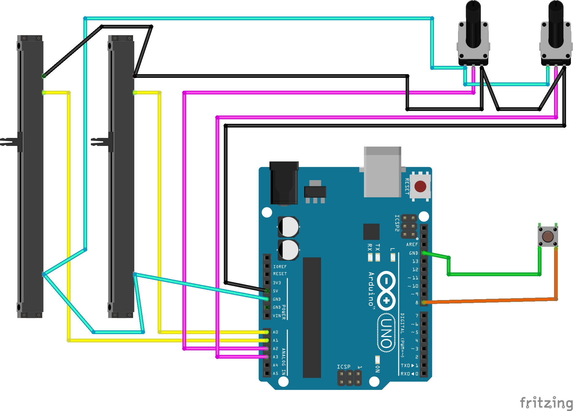
- carte Arduino Uno / Seeduino
- bouton poussoir
- 2 potentiomètres rotatifs
- 2 potentiomètres slider
Intentions : explication du projet et objectifs
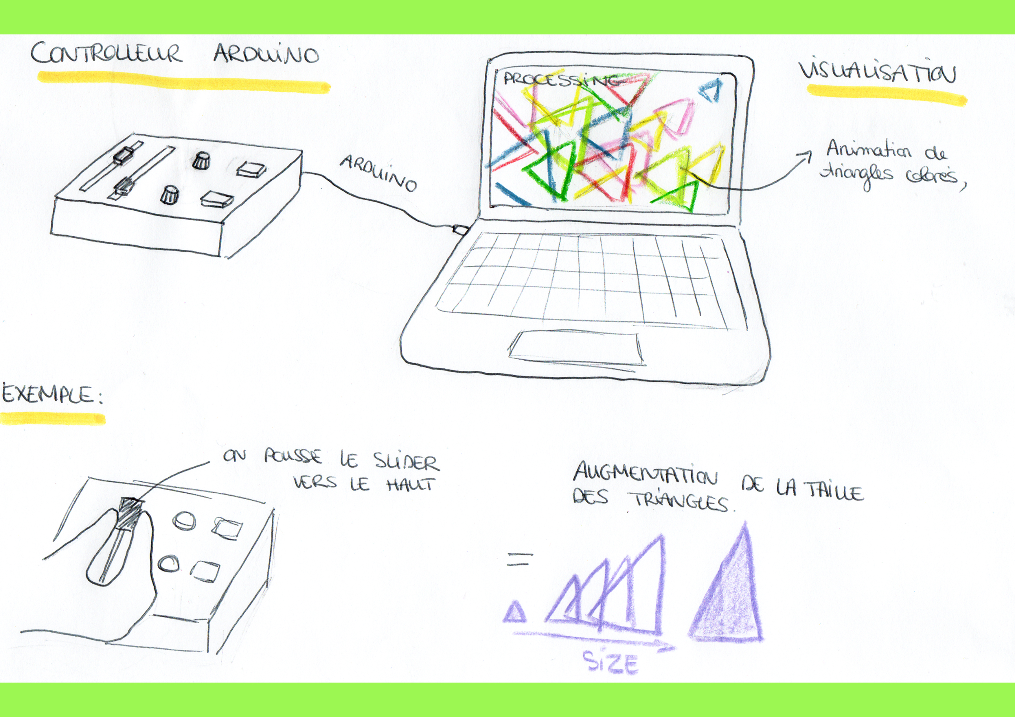
Mon intention est de créer un contrôleur midi pour images. Partant du principe que designer graphique et musiciens utilisent des outils communs (l’ordinateur par exemple) mais pour des usages différents.
L’idée est de pouvoir gérer du visuel en interaction avec la musique, grâce à un contrôleur midi constitué de deux slider, deux potentiomètres, et un bouton poussoir. Ce mini boitier sera relié à un programme processing de visualisation sonore et permettra ainsi à l’usager de modifier le visuel selon sa propre interprétation de la musique. Il pourra ainsi accentuer une forme à un moment modifier les couleurs à un autre.. tout cela grâce au contrôleur. Mon but est de transposer un outil largement utilisé dans le domaine de la musique électronique dans le domaine du graphisme, tout en gardant sa forme. Le graphiste peut ainsi apporter son propre « mix » visuel à partir de la musique qu’il écoute.
Plans et schémas de fonctionnement
Programmes
Arduino
essai 1 / SerialCallResponse
int potentiometre1 = A0;    // first analog sensor
int potentiometre2 = A1;
int potentiometre3 = A2;
int potentiometre4 = A3;
int bouton = 8;          // digital sensor
int inByte = 0;         // incoming serial byte

void setup() {
  // start serial port at 9600 bps:
  Serial.begin(9600);
  while (!Serial) {
    ; // wait for serial port to connect. Needed for native USB port only
  }

  pinMode(8, INPUT);   // digital sensor is on digital pin 8
  establishContact();  // send a byte to establish contact until receiver responds
}

void loop() {
  // if we get a valid byte, read analog ins:
  if (Serial.available() > 0) {
    // get incoming byte:
    inByte = Serial.read();
    // read first analog input, divide by 4 to make the range 0-255:
    potentiometre1 = analogRead(A0) / 4;
    // delay 10ms to let the ADC recover:
    delay(10);
    // read second analog input, divide by 4 to make the range 0-255:
    potentiometre2 = analogRead(A1) / 4;
    delay(10);
    potentiometre3 = analogRead(A2) / 4;
    // delay 10ms to let the ADC recover:
    delay(10);
    // read second analog input, divide by 4 to make the range 0-255:
    potentiometre4 = analogRead(A3) / 4;
    // read switch, map it to 0 or 255L
    bouton = map(digitalRead(8), 0, 1, 0, 255);
    // send sensor values:
    Serial.write(potentiometre1);
    Serial.write(potentiometre2);
    Serial.write(potentiometre3);
    Serial.write(potentiometre4);
    Serial.write(bouton);
  }
}

void establishContact() {
  while (Serial.available() <= 0) {
    Serial.print('A');   // send a capital A
    delay(300);
  }
}
Processing
J'ai trouvé ce programme https://github.com/amygoodchild/spinningtriangles_midicontroller/blob/master/Triangle.pde qui fonctionne avec les touches du clavier que je souhaiterai adapté pour mon contrôleur.
import processing.serial.*;
// variables pour stoquer les données arduino (au nombre de 5)

// variables triangles
float widthgap;
float heightgap;
int cols = 23;
int rows = 11;
int numOfTriangles;
Triangle[] triangles;
float animationSpeed = 50;
float backgroundOpacity = 100;


Serial myPort;  // The serial port
int Narduino = 5; // nombre de données envoyées par la carte Arduino
int[] serialInArray = new int[5];    // Where we'll put what we receive
int serialCount = 0;
int xpos, ypos; // A count of how many bytes we receive

boolean firstContact = false;        // Whether we've heard from the microcontroller

void setup() {
  size(1920, 1080, P3D);
  //fullScreen(P3D);
  colorMode(HSB, 100);
  background(0);
  smooth();


  serialInArray= new int[Narduino];

  // initialisation des variables arduino
  widthgap = 100;
  heightgap = 100;
  numOfTriangles = cols*rows;
 ;

  // Print a list of the serial ports, for debugging purposes:
  printArray(Serial.list());

  // I know that the first port in the serial list on my mac
  // is always my  FTDI adaptor, so I open Serial.list()[0].
  // On Windows machines, this generally opens COM1.
  // Open whatever port is the one you're using.
  String portName = Serial.list()[4];
  myPort = new Serial(this, portName, 9600);


  triangles = new Triangle[numOfTriangles];
  for (int i=0; i<numOfTriangles; i++) {
    int row = i/cols;
    int col = i%cols;
    triangles[i] = new Triangle(col, row, i);
    triangles[i] = new Triangle(col, row, i);
  }
}

void draw() {
  // dessin d'un cecle coloré avec les valeurs de la carte Arduino
  fill(0, 0, 0, backgroundOpacity);
  translate(-width*2, -height*2, -500);
  rect(0, 0, width*5, height*5);
  translate(width*2, height*2, 500);

  for (int i=0; i<numOfTriangles; i++) {
    triangles[i].update();
    if (triangles[i].row < rows && triangles[i].col < cols) {
      triangles[i].display();
    }
  }
}

void serialEvent(Serial myPort) {
  // read a byte from the serial port:
  int inByte = myPort.read();
  // if this is the first byte received, and it's an A,
  // clear the serial buffer and note that you've
  // had first contact from the microcontroller.
  // Otherwise, add the incoming byte to the array:
  if (firstContact == false) {
    if (inByte == 'A') {
      myPort.clear();          // clear the serial port buffer
      firstContact = true;     // you've had first contact from the microcontroller
      myPort.write('A');       // ask for more
    }
  } else {
    // Add the latest byte from the serial port to array:
    serialInArray[serialCount] = inByte;
    serialCount++;

    // If we have 3 bytes:
    if (serialCount > Narduino-1 ) {
      for (int i=0; i<numOfTriangles; i++) {
      triangles[i].newSize = serialInArray[0];
      triangles[i].innerOpacity = serialInArray[1];
      backgroundOpacity = serialInArray[2];
      triangles[i].newHueOffset  = serialInArray[3];
      ypos = serialInArray[4];

      // print the values (for debugging purposes only):
      println(triangles[i].newSize + "\t" + triangles[i].innerOpacity + "\t" + backgroundOpacity + "\t" + triangles[i].newHueOffset);

      // Send a capital A to request new sensor readings:
      myPort.write('A');
      // Reset serialCount:
      serialCount = 0;
    }
  }
}
}
Améliorations
Le problème que j'ai rencontré c'est un manque de réactivité entre mon geste et le résultat obtenu sur processing, le but étant justement de pouvoir créer et modifier du visuel en live il vaudrait peut-être mieux envoyer directement des valeurs plutôt que des A.
Références : DIY midi controller
Je me suis beaucoup inspirée de la série de vidéos suivante : https://youtu.be/kESotTqQgm4
Réalisation de la maquette
vidéos, photos du making of…


